- Part 1 – Setting up Fabric Interconnect, and UCS Manager settings
- Part 2 – Configuring Connectivity & Setting up the policies and Service Profiles
- Part 3 – Deploying ESXi via KVM onto FlashFlex (SDCard)
- Part 4 – Upgrading the Firmware
First off, huge thanks to the following posts by Rene Van Den Bedem and his Cisco UCS installation guide.
My aim here is not to rip off his posts, but to detail the process myself and use my own screenshots, as along the way, the setup was slightly different to Rene’s, such as the configuration needed for the SD Cards, and the lack of boot from SAN configuration.
Covered in Part 1;
- The hardware/software
- Cabling diagram
- Pre-Reqs
- Understanding Cisco’s policy based management
- Summary of Task List
- Setting up Fabric Interconnects
- Connecting to Cisco UCS Manager
The Hardware/Software
First off, we have the following hardware;
- UCS Chassis
- 2 x 6248 Fabric Interconnects
- 4xB200M4 blades
- 2 x 32GB SD Cards per blade
- 1 x VIC 1240 per blade
- 1 x Nimble CS300
The deployment will be based upon;
- VMware vSphere 6.0
- VMware vRealise Operations Manager 6.2
Over all, we will be using the existing networking in place, which is made up of HP Procurve devices.
Cabling Diagram
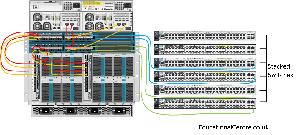
A quick diagram to show how the devices were all connected up, the connections between the FI and the Chassis are coloured differently to define the overlapping cables in the diagram, and do not indicate any special separate configuration.
For the Nimble, each controller should have one connection to each FI. (Please visit this post for setting up a Nimble from scratch)
For the LAN switch connections, if you have a single stacked switch, then try to cable so that redundant connections are across different switches in stack. If you have two separate switches (switch stacks) then you should connect a FI per switch (switch stack).
Pre-Reqs
- You need anyroutable IP address pool for;
- KVM of Blades (one per blade)
- 3 x Fabric Interconnect Management (1 Floating, 2 for local)
- 3 x Nimble Management (1 floating/array, 2 diagnostics)
- X for ESXi management
- You need a nonroutable IP address pool for;
- X x Nimble Data ports
- X x ESXi iSCSI VMKernel Ports
Secure password’s for;
- Fabric Interconnect; Admin account
- Nimble Management: Admin account
- ESXi hosts: Root account
- Domain User (Service account) for VMware
- Domain User to provide LDAP Authentication for Cisco UCS Login
A management machine which has Java and Flash installed.
Policy Based Management
The reason why Cisco UCS is so different to traditional hardware deployments is due to the upfront policy based management nature.
You set all your policies first, such as QOS, created your ID pools, for things such as IP addresses, iSCSI IQNs, WWNN, Mac Addresses and so forth. You create your virtual network interfaces that will be available on the blade servers, and which networks they can contact via the Fabric Interconnects.
Once done, you create Service Profiles which consist of the various policies you require, I.e policies specific for an ESXi install. You deploy this profile, and associate your various hardware against the profile.
Should a blade server die, you can simply replace the hardware, and not have to think about the reconfiguration needed to get it working, as all the hardware identifiers and policies will remain and be applied.
Summary task list of configuration
In this environment I’ll be covering;
- setting up the fabric interconnects
- Setting up AD authentication
- Setting up Email Alerts
- configuring the fabric interconnect ports to LAN, SAN and Chassis
- setting up the chassis and blade servers initially
- firmware updates
- configuring the policies needed for ESXi deployment
- configuring the virtual NIC templates
- creating a service profile template and deploying service profiles
- setting up dual SD cards in flexmode
- setting up the Nimble storage for iSCSI VMFS volumes
Setting up the Fabric Interconnects
Cable up the front of your FIs, as below,
Power on what will be Fabric A, but leave Fabric B turned off.
Connect to the fabric interconnect using serial cable, and the usual Cisco switch settings (9600 baud, everything else should be the same if you are using putty).
Once loaded you will go through the following steps;
Enter the configuration method. (console or gui) ?: console
You have chosen to setup a new Fabric interconnect. Continue? (y/n): y
Enforce strong password? (y/n): y
Enter and confirm your password
Is this Fabric interconnect part of a cluster (select ‘no’ for standalone)? (yes/no): yes
Enter the switch fabric (A/B): A
Enter the system name: System_Name
Physical Switch Mgmt0 IPv4 address: IP_Address
Physical Switch Mgmt0 IPv4 net mask: Subnet_Mask
IPv4 address of the default gateway: Default_Gateway
Cluster IPv4 address: Floating_Management_IP_Address
Configure the DNS Server IPv4 address (yes/no): yes
DNS Server IPv4 address: DNS_IP_Address
Configure the default domain name? (yes/no): yes
Default domain name?: Domain_Name
You will then be given confirmation of settings you have configured
Apply and save the configuration(select ‘no’ if you want to re-enter)? (yes/no): yes
Once applied you will be given a prompt similar to;
System_Name-A login:
Verify you can ping the Fabric Interconnect from your LAN.
Boot Fabric B, connect the console cable, and when prompted;
Enter the configuration method. (console or gui) ? console
Installer has detected the presence of a peer Fabric interconnect. This Fabric interconnect will be added to the cluster. Continue (y/n)? y
Enter the admin password for the peer Fabric interconnect: Admin_Password
Connecting to peer Fabric interconnect… done
Retrieving config from peer Fabric interconnect… done
Physical Switch Mgmt0 IPv4 address: IP_Address
You will then be given confirmation of settings you have configured
Apply and save the configuration(select ‘no’ if you want to re-enter)? (yes/no): yes
Once applied you will be given a prompt similar to;
System_Name-B login:
Once done, confirm you can ping the IP address of Fabric B.
Connecting to UCS Manager
Now your ready to connect to Cisco UCS Manager, so launch a browser to https://Floating_IP_Address
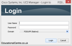
Click Launch UCS Manager, and then provide the credentials for the “Admin” account.
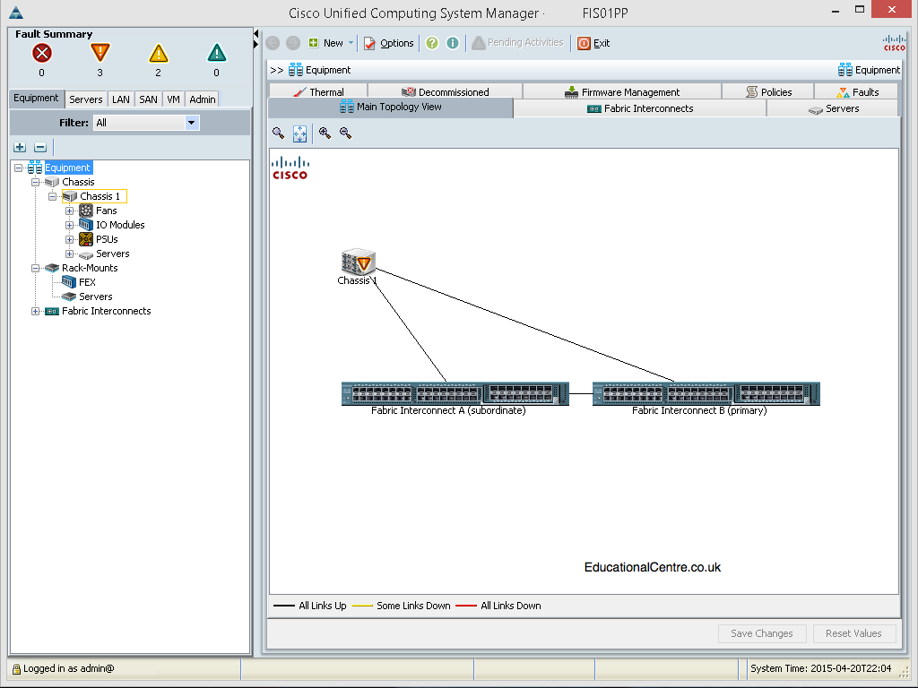
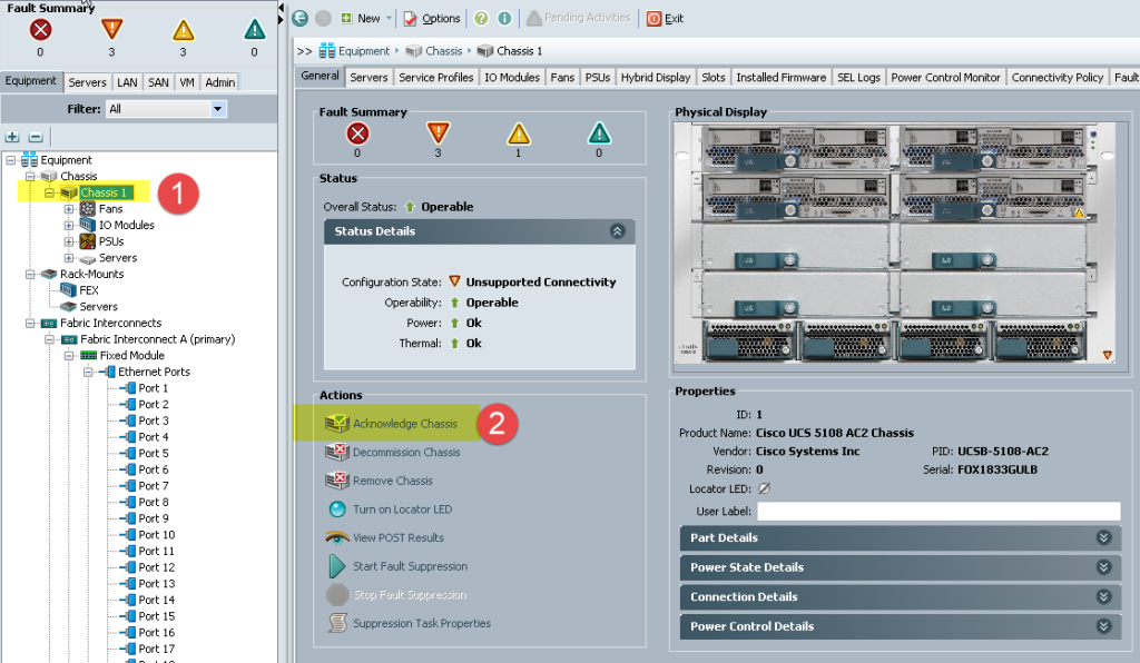
and Viola, the UCS Manager interface is ready, well once you acknowledge the chassis and blade servers, see the second screenshot.
Getting around the interface
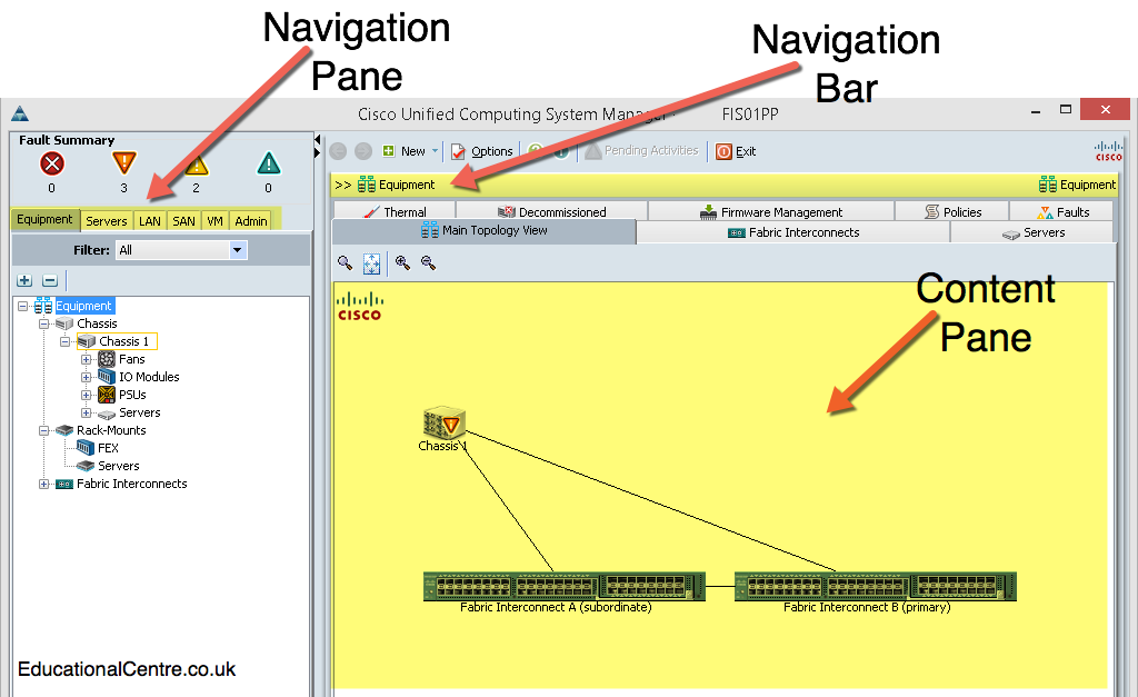
Ok, so lets look at the interface, which is made up of the following headline tabs, which take you into different aspects of the UCS configuration;
- Equipment
- Servers
- LAN
- SAN
- VM
- Admin
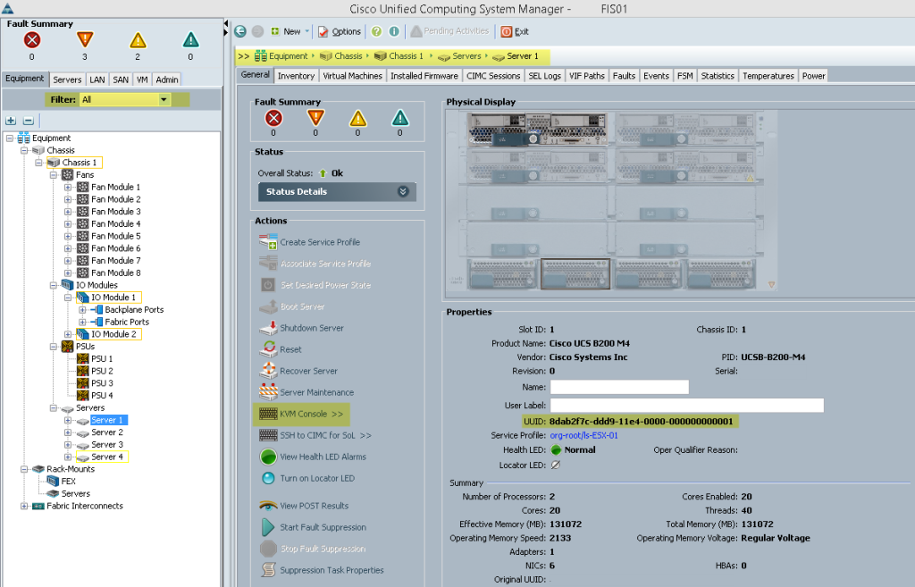
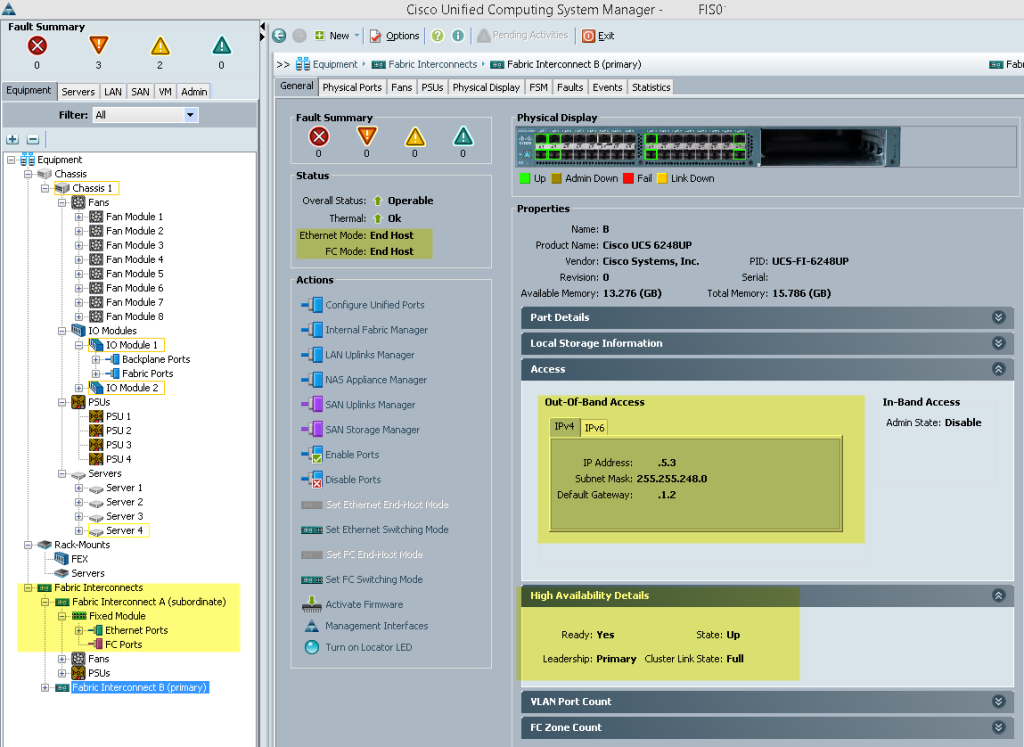
Equipment; is a hierarchical list that shows chassis (1 to 40) and Fabric Interconnects (A + B), further subcomponents such as nodes (blades or rack servers) and interface cards can be delved into further. When an object is highlighted, the attributes are shown in the content pane (right hand side). The navigation pane has a selection menu which can be used to show all objects available, or restrict the objects in view.
I’ve highlighted some area’s of interest, such as remote KVM to a blade, the switching mode of the FIs, and so forth.
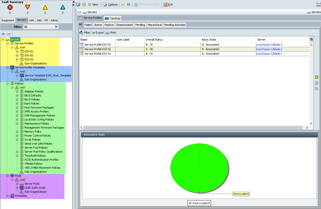
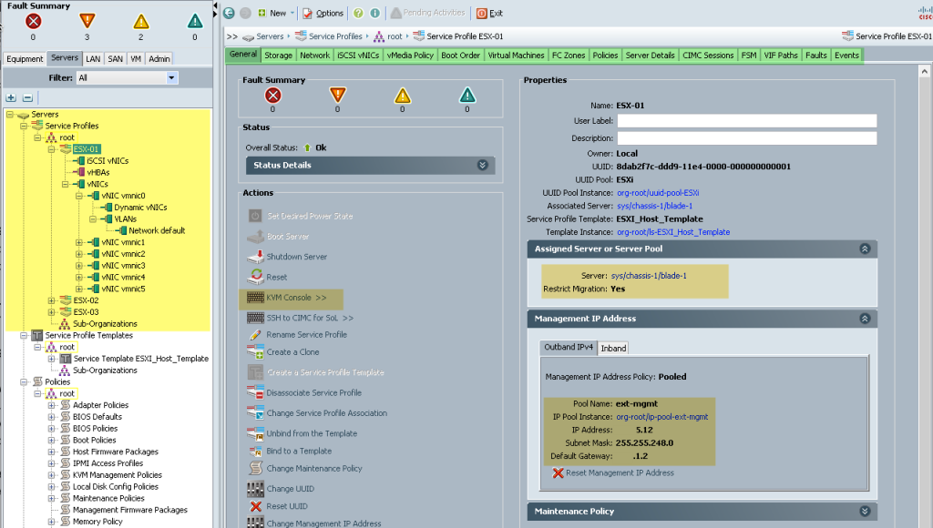
Servers; contains all server related components, for example, service profiles, policies and pools. Here you can configure Organisations, Service Profiles and templates, pools and policies.
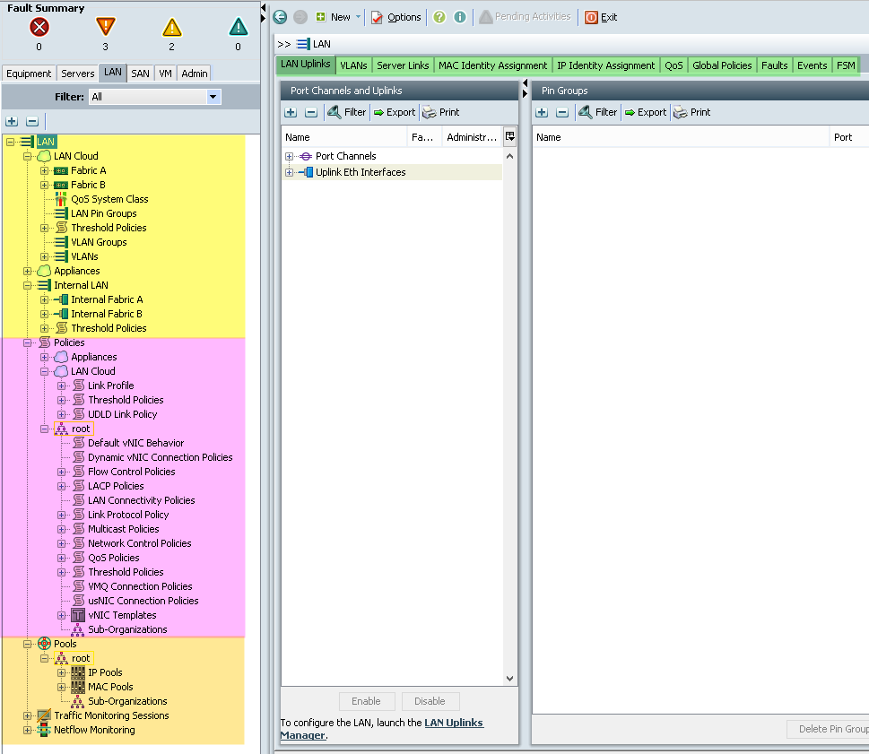
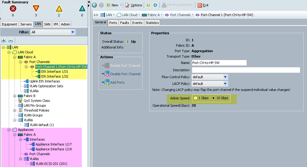
LAN; contains all LAN configurations; pin groups, QoS, VLANs, policies surrounding the network configuration, pools (IP, MAC, IQN).
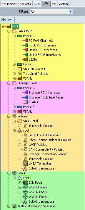
SAN; Storage area network configurations; pin groups, VSANs, policies, and pools.
I’ve tried to split up the different Area’s of configuration under each tab, as I’ve not used the SAN configuration parts for my setup, there is little to show, however see Rene’s post for a more in-depth view.
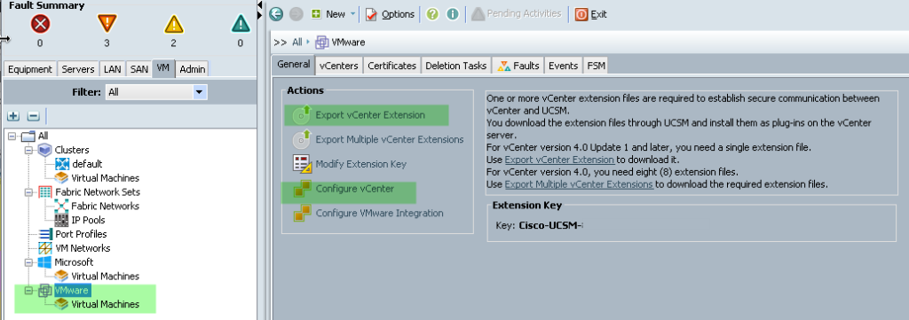
VM; contains all the configurations needed for VM-FEX hardware switching, which can be used on servers that have a VIC card installed. Here you configure a connection to the VMware vCenter server, and then configure Distributed Virtual Switches, port profiles and be able to view the VMs that run on each UCS Server.
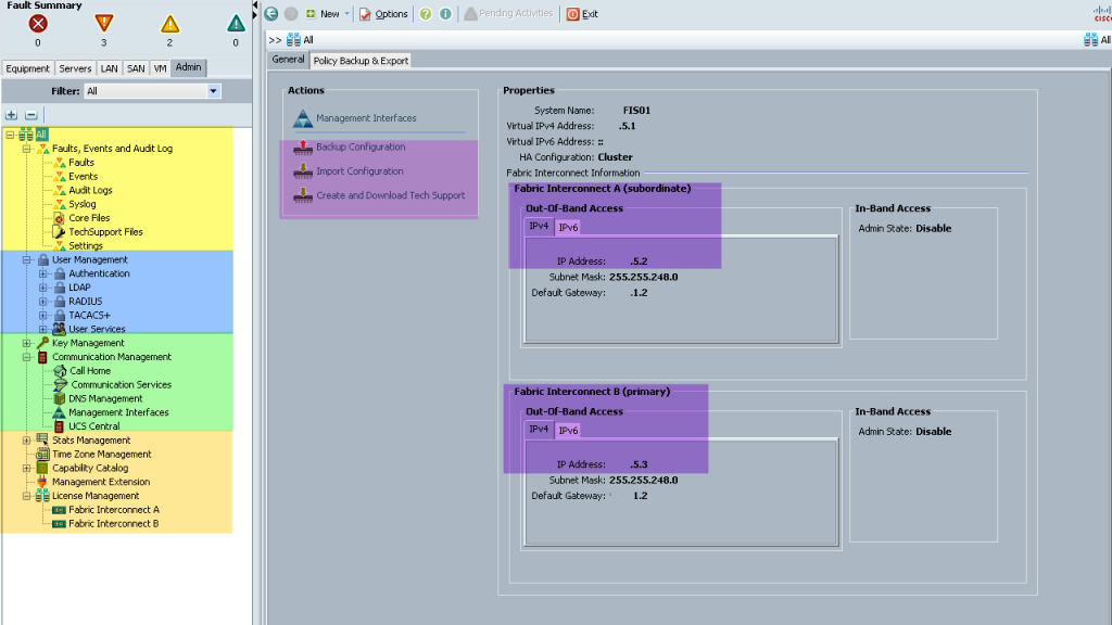
Admin; UCS System-wide settings are found here, setting up user access, LDAP Authentication, Email Alerts and so forth.
So this concludes the first post, next up in part 2 we will be creating the networking for the chassis and then creating service profiles to give our blade servers and identity.
Regards
Dean



good, thx
cheers for the feedback
Great write up, keep up the good work!
Thank you!
You should make your screenshots a bit bigger so we don’t have to click on them 🙂
I’ll look at resizing a few of the really small ones, however if I post them at full size, they are too big and make the pages unappealing to most visitors unfortunately.
I do agree that larger pictures would be nice. I had to click to open each one to see what was going on.
Hi, I will be reviewing the content in the posts as there are a few changes to be made, so I’ll look at picture sizing, as I’m getting feedback about both ways for the image sizes at the moment, some would like them bigger, some like them the way they are.
6948 Fabric Interconnects
This a typo? Didn’t recognize the model number and couldn’t find it on Cisco site (6248 for example exists).
Yes this is a typo, I’ll get it changed, cheers 🙂
Thanks Dean, we are looking at deploying UCS next year on top of our HP networking stack also so this will prove very useful for us.
Hi, this is really great to hear, thanks for the comment, I hope all goes well for your install.
This is great. I’ve been hearing about UCS but never really got it. This documentation style is perfect for my mindset as I can read and see it as if I were doing it myself.
thanks for the feedback
Tonight I downloaded the UCS Platform Emulator and was able to walk through all of your steps, doing the actual clicks myself. Makes it all the better: https://communities.cisco.com/ucspe
This is great to know, thanks for the feedback, as I’ve not actually tried the same in depth configuration in the emulator, just used the emulator to get used to the interfaces etc
I used the 2.2.4b version as it is the closest to what is in place at work. The only thing that didn’t work was as I created the VLANs, they weren’t appears under the VLAN section of the FI, even though I had them selected for both.
If you select the VLANs to be on both FI’s, they won’t appear under the expanded menus per FI, just globally
if you select a VLAN to be against a specific FI, then it will appear under only that FI and not globally
Good guide. Id recommend doing the firmware before you install esx though. Some blades need an update to support certain versions of esxi.
Good point, I’d already wrote the first three parts as they were, then the part 4 came right at the last minute, hence the order, but I’ll drop in a note on part 3!
That was really a very good write up.! You spend quite some time to write it up. If possible can also mention about the Fabric Interconnect modes I mean End-Host mode & Switch mode configurations ?
Thanks……….
Firstly thank you for the feedback!!! It is really appreciated,
For the FI modes, I could possibly post something, I didn’t have time originally and didn’t want to detract from the post, as switching mode is really advised against in most deployment scenarios, this is why I linked to Cisco’s official information on the matter,
I may write something up as a separate post, then reply back here so you get notified, or you could subscribe to my blog.
Regards
Dean
Have to say, really impressed with the content , thank you for taking the time to put it together.
thank you for your feedback! Really great to hear that my content is helping people